How to make a homemade single plane. We make cool flying paper airplanes with children. Paper long-range fighter
Good day everyone! How are you guys and girls? In the last article, we did it with you, and in this one we will make the plane of your dreams))). True, it will be made of paper, but such that it flies fast and far and no one can catch it.
And then you can arrange a competition and let all the paper planes rush to the distillation, how do you like this idea? Probably just great, because spring is coming soon, and there will be summer, when there will be much more fun and entertainment than now.
Everyone knows this toy, even kids, who also love and willingly sit and fold A4 sheets with great interest to get a wonderful craft and at the same time a flying machine above the ground.
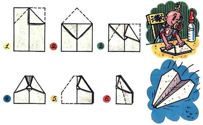
The easiest way is familiar to all of us from childhood, absolutely everyone remembers it, both moms and your dads. Take a look at this picture.
First of all, we will make such an airplane that flies far, the main thing is that it flies straight and beautiful. Just what you need to have fun and be able to watch him))).
We will need:
- A4 sheet - 1 pc.
Stages of work:
1. Take a sheet, our toy will be made from it. Decide on the color, you can take a traditional white sheet, or you can take, for example, green or blue.

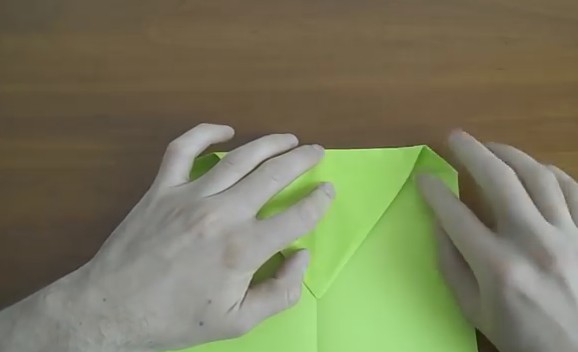
2. Lay the paper horizontally in front of you and fold it in half. We will do it using the origami technique.

3. Then open and rotate vertically. Begin to bend to a straight line.

4. Thus, at the top you get a triangle.

5. Now fold the resulting line back to the outside. Do this on both sides.

6. Repeat the steps again.
7. This is what should happen.

8. Then open all folded parts.

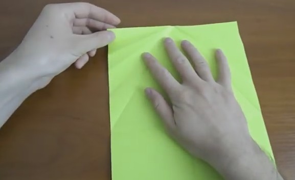
9. Fold the paper on both sides, where you have two marked lines to the center strip.

10. At the intersections, fold the sheet of paper forward.

11. Press the line with your fingers.
12. Open and return the sheet to its original position.
13. After bending along the first top line.

14. Fold to the center horizontal line.

15. Place the resulting corner exactly on the line.
16. Then turn the sheet over and fold along a horizontal line.

17. Turn the sheet over again to the other side and make the triangle look up.

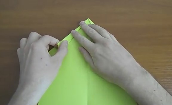
18. Bend the upper parts of the center line, when you begin to do this, the product will begin to gather.

19. Therefore, you have to push the paper very carefully with your own hands.

20. You need to do these actions from two sides.

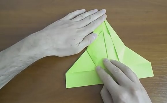
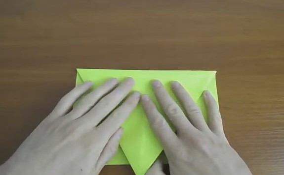
21. Fold in half in half.

22. Bend the airplane's wings.

23. After, on the wings themselves, make folds of 1-1.5 cm.

24. Open the airplane and align your wings. Here is such a handsome man turned out, and ready to fly. Look, just don't fly too far))).

Origami paper plane in 5 minutes
For the smallest fidgets, there is of course a simpler instruction, such souvenirs turn out just as well and they also fly very well, depending on how you launch, you can not catch up and fly away hoo as 100 meters, you are tormented to look for later).

Most importantly, you need to make the two sides the same in the mirror image so that they turn out to be even and then everything will work out for sure.
On one of the forums, I looked at a craft called Piranha, and it looks like the truth? Also, the author chose the color red. See how cleverly you can turn such a miracle. No special skills are required. The most primitive version with a simple model.

It turned out to be a cool little thing, my boys really liked it).

By the way, you can get a little creative and give dad a little surprise.

In general, do such a craft with your child so that there is something to do in the circle of your beloved family, because such work is very close.

Step-by-step instructions for a flying toy for beginners
It is interesting that almost any aircraft can fly a sufficient number of meters above the ground, it can be 10,000 and even more than 1,000,000, the most important condition is, depending on what height it will be launched from and whether there will be wind outside and how it will pick it up.
If you want your airplane to never fall over, then use this scheme. Such a toy will show you a uniform and very fast flight. You yourself will be very surprised.

If you like such air transport with big wings, then fold this kind of airplane.

You can also build with a blunt nose, there will be no collisions for this.

Well, if you don’t understand diagrams and instructions at all, then watch this step-by-step video from the YouTube channel:
How to make a paper plane that will fly very far up to 10,000 meters?
In fact, there are a fairly large number of various paper models of this air transport. The leaders at the moment are the Hawk, Eagle Owl, Falcon and Albatross.
And this is not all to say, I propose to lay down a powerful and beautiful airplane called Thunderstorm.
Stages of work:
1. Be sure to bend a sheet of paper symmetrically, spread the resulting line very well with your hands, then turn it back.

2. Make a triangle at the top, as we did in the first example.

3. Bend the leaf to the center again on both sides, you get a sharp triangle.

4. Then bend the sheet where the fold point formed.


6. Next, roll the triangle forward again.

7. Turn over the resulting masterpiece and bend again.

8. Bend the plane in half. Bend the top of the wings a little, as shown in the photo.

9. And then bend so that you get real ones, like an airplane.

10. Voila, and that's what happened, it looks cool and cool, but how it cages, well, it's definitely fast and far).

DIY paper airplane model for kids with folding patterns
Do you want to make a bunch of beautiful and pretty sharp or blunt-nosed airplanes with your kids?
First of all, learn how to make these yourself, and then teach your little helpers this easy task. Start with the simplest model.
If you do not understand this scheme, go to the next one and choose.

We make a Glider from an A4 sheet easily and simply
If you want another look, which is obtained in a matter of minutes, and it will not be necessary to fold and bend much, a completely different technique is used. It turns out cool and original. In general, a cool option for a child who will gladly launch it in the air.
We will need:
- paper
Cooking method:
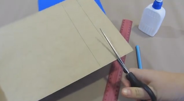
1. Bend sheet A4 in half and draw a line well with your hands. Take scissors or a clerical knife and cut along it.

2. You will get two small leaves, fold one sheet in half again and draw a blank with a pencil, which you can ask me for free, and then print it on your printer.

3. Cut out the template and don't forget to make gaps on the wings and tail as shown in the picture I sent you.


5. Take your time, iron the lines neatly and evenly.

6. There is no need to hurry, otherwise it will turn out to be a blunder.

7. Put a piece of plasticine into the nose of the air transport and close it.

8. Where the cuts were made on the tail, bend and straighten the paper.

9. Do the same with the wings.

10. To give flying ability, you need to smooth out the wings with a pencil and wrap them up a little.

11. It should turn out something like this. To test the elevator, lower the plane vertically down, it should take off like the wind, but don't overdo it.

If your plane tends to one of their sides, then adjust it, because you can lower or raise the traffic controllers.
Volumetric cardboard craft
We will need:
- cardboard - 2 sheets
- PVA glue
- ruler
- pencil
- scissors
- Matchbox

Stages of work:
1. Mark two strips on cardboard with a pencil, their width should be equal to a matchbox.
2. Then cut them out with scissors. From these strips make the wings of the plane. On another sheet, mark two strips 1.5 cm wide and also cut them along the length of the cardboard.

Move one such thin strip aside, and cut the second into two parts of 8 cm each, remove the rest, it will not be needed. Here's what happens:

3. Now start building. Take a matchbox, bend a long thin strip in half and attach, glue it to the box.

4. With the help of two identical strips that are wide, like boxes, make wings.

The corners can be rounded, cut them with scissors.
5. From one short narrow strip, make a tail and also round it, glue it inward. And glue the second one on top, make a triangle out of it.

6. After you can cut the propeller and glue it.

7. The craft is ready, enjoy your work!

Video on how to roll a Fighter without glue

Of course, it will be difficult to do such a craft if you are doing it for the first time, so I suggest starting by watching a video that will definitely teach you how to create such a charm.
Well, how did it work out for you? Is it really easy and simple and also without glue, and not difficult, as at first glance?
And if you have problems with the Internet, then you can always use the scheme, especially if you suddenly forget something, too, as an option.


P.S. By the way, craftsmen even make such airplanes from one match, see for yourself:
Well, that's all I have. I wish you creative success and good luck! Create for health, play and rejoice! All the best and joyful. Bye everyone!
You decide to build an airplane. And immediately before you the first problem - what should he be? Single or double? Most often, this depends on the power of the existing engine, the availability of the necessary materials and tools, as well as the size of the "hangar" for building and storing the aircraft. And in most cases, the designer has to opt for a single-seat training aircraft.
According to statistics, this class of aircraft is the most massive and popular among amateur designers. For such machines, a variety of schemes, types of structures and engines are used. Equally common are biplanes, low-wing and high-wing monoplanes, single- and twin-engine, with pulling and pushing propellers, etc.
The proposed series of articles contains an analysis of the advantages and disadvantages of the main aerodynamic schemes of aircraft and their design solutions, which will allow readers to independently assess the strengths and weaknesses of various amateur designs, help to choose the best of them and the most suitable for construction.
WITH AIRCRAFT - ONE TO ONE
One of the most common schemes for an amateur single-seat aircraft is a strut-braced monoplane with a high wing and a tractor propeller. It should be noted that this scheme appeared in the 1920s and has not changed much over the entire period of its existence, becoming one of the most studied, tested and constructively worked out. The characteristic features of an aircraft of this type are a wooden two-spar wing, a welded steel truss fuselage, linen sheathing, a pyramidal landing gear and a closed cockpit with an automobile-type door.
In the 1920s - 1930s, a variation of this scheme became widespread - an aircraft of the "parasol" type (from the French parasol - an umbrella from the sun), which was a high-wing aircraft with a wing fixed on racks and struts above the fuselage. "Parasols" in amateur aircraft construction are still found today, however, as a rule, they are structurally complex, less aerodynamically perfect and less convenient to operate than classic high-wing aircraft. In addition, such devices (especially small ones) have very difficult access to the cabin and, as a result, the difficulty of its emergency escape.


Single-seat high-wing aircraft:
Engine - LK-2 with a power of 30 hp. designs L. Komarov, wing area - 7.8 m2, wing profile - Clark, take-off weight - 220 kg (pilot - 85 kg, power plant - 32.2 kg, fuselage - 27 kg, landing gear with skis -10.5 kg , horizontal tail - 5.75 kg, wing with struts - 33 kg), maximum speed - 130 km / h, flight range with a fuel reserve of 10 l-180-200 km
Engine - Zündapp with a power of 50 hp, wing area - 9.43 m2, take-off weight - 380 kg, empty weight - 260 kg, maximum speed -150 km / h, rate of climb near the ground - 2.6 m / s , flight duration -8 h, stall speed - 70 km/h

The advantages of high-wing aircraft include the simplicity of piloting technique, especially if the specific load on the wing does not exceed 30 - 40 kg / m2. High-wing aircraft are distinguished by good stability, excellent takeoff and landing characteristics, they allow rear centering up to 35-40% of the mean aerodynamic chord (MAC). From the cockpit of such an apparatus, the pilot is provided with an optimal downward view. In short, for those who are building their first aircraft, and besides, they are going to master its piloting on their own, there is no better scheme to come up with.
In our country, amateur aircraft designers have repeatedly turned to the scheme of a strut high-wing aircraft. So, at one time a whole squadron of “parasol” aircraft appeared: “Kid” from Chelyabinsk, created by the former pilot L. Komarov, “Leningradets” from St. .Frolov from the village of Donino near Moscow.
The last device should be told in more detail. Having well studied the simplest scheme of a high-wing strut, the designer carefully planned his work. The wing was made of pine and plywood, the fuselage was welded from steel pipes and these elements of the aircraft were covered with canvas according to classical aviation technology. I chose large wheels for the landing gear so that I could fly from unprepared unpaved grounds. The power unit is based on a 32-horsepower MT-8 engine, equipped with a gearbox and a large-diameter propeller. Aircraft takeoff weight - 270 kg, flight centering - 30% MAR, specific wing load - 28 kg / m2, wing span - 8000 mm, propeller thrust in place - 85 kgf, maximum speed - 130 km / h, landing speed - 50 km /h
Test pilot V. Zabolotsky, who flew around this device, was delighted with its capabilities. According to the pilot, even a child can control it. The aircraft was operated by V. Frolov for more than ten years and participated in several ULA rallies.
The PMK-3 aircraft, created in the city of Zhukovsky near Moscow by a group of amateur aircraft designers led by N. Prokopts, caused no less delight among the test pilots. The car had a peculiar forward fuselage, a very low landing gear and was designed according to the scheme of a strutted high-wing aircraft with a closed cockpit; a door was provided on the left side of the fuselage. The wing is slightly beveled back to provide the necessary centering. The design of the aircraft is solid wood, covered with fabric. The wing is single-spar, with pine shelves, a set of ribs and a wing forehead are sheathed with plywood.

Wing area - 10.4 m2, wing profile - R-Sh, takeoff weight - 200 kg, fuel capacity - 13 l, flight centering - 27% MAH, static propeller thrust - 60 kgf, stall speed - 40 km / h, maximum speed - 100 km / h, flight range - 100 km
The basis of the fuselage - three spars, and therefore the fuselage had a triangular cross section. The plumage and control system of the PMK-3 aircraft are made as in the well-known training glider B. Oshkinis BRO-11 M. The basis of the power plant is a 30-horsepower liquid-cooled outboard motor "Vikhr"; while the radiator protruded slightly from the starboard side of the fuselage.
An interesting variety of amateur-built strutted high-wing aircraft was the Don Quixote, developed in Poland by J. Yanovsky. With the light hand of an amateur aircraft industry enthusiast, a well-known glider test pilot and journalist G.S. Malinovsky, who published the drawings of Don Quixote in the Modeler-Konstruktor magazine, this, in general, not entirely successful scheme, was very widespread in our country - at times there were more than four dozen similar devices at ALS rallies. True, professional aircraft designers believe that amateur aviators in this scheme were attracted primarily by the unusual appearance of the aircraft, but it was in it that some “pitfalls” lurked.
A characteristic feature of the "Don Quixote" was the forward cockpit, which provided excellent visibility and comfortable accommodation for the pilot. However, on an extremely light aircraft weighing up to 300 kg, the balance changed significantly when a more slender pilot, weighing 60 kg, sat in the cockpit instead of an 80-kg pilot - while the device suddenly turned from excessively stable into absolutely unstable. It was necessary to avoid such a situation even when designing the machine - it was only necessary to install the pilot's seat in the center of its gravity.


Aircraft with a pusher propeller, designed according to the scheme of the Don Quixote aircraft:
Engine power - 25 hp, wing area - 7.5 m2, empty weight - 150 kg, takeoff weight - 270 kg, maximum speed - 130 km / h, rate of climb near the ground - 2.5 m / s, ceiling - 3000 m, flight range - 250 km. Machine structure - solid wood
Engine power - 30 hp, wing span -7 m, wing area - 7 m2, empty weight - 105 kg, takeoff weight - 235 kg, maximum speed - 160 km / h, rate of climb - 3 m / s, flight duration - 3 h
Construction - fiberglass, engine power - 35 hp, wing span - 8 m, wing area - 8 m2, wing profile - Clark YH, takeoff weight - 246 kg, empty weight - 143 kg, flight centering - 20% MAR, maximum speed - 130 km/h
Another feature of the Don Quixote is the tailwheel landing gear. As is known, such a scheme, in principle, does not ensure the directional stability of a light aircraft when it moves along the airfield. The fact is that with a decrease in its mass and moments of inertia, the movements of an aircraft become fast, sharp, short-term, and the pilot has to concentrate all his attention on maintaining the direction of the takeoff or run.
The A-12 aircraft from the Aeroprakt club (Samara), which was one of the copies of Don Quixote, had exactly the same birth defect as the first-born of this galaxy, but the designers, after testing the machine by professional pilots V. Makagonov and M Molchanyuk quickly found an error in the design. By replacing the tail wheel with a nose wheel on the A-12, they completely eliminated one of the main drawbacks of the Polish aircraft.
Another significant drawback of Don Quixote is the use of a pusher propeller, shaded in flight by the cockpit and wing. At the same time, the efficiency of the propeller dropped sharply, and the wing, which was not blown by the air flow from the propeller, did not provide the calculated lift. As a result, takeoff and landing speeds increased, which led to a lengthening of the takeoff run and run, and also reduced the rate of climb. With a low thrust-to-weight ratio, the aircraft could not take off from the ground at all. This is exactly what happened at one of the ALS rallies with the Elf aircraft, built according to the Don Quixote scheme by students and employees of the Moscow Aviation Institute.
Of course, it is not forbidden to build devices with a pusher propeller, however, the need and expediency of creating an aircraft with such a power plant in each specific case should be carefully evaluated, since losses in thrust and wing lift are inevitable.
It should be noted that designers who creatively approached the use of a power plant with a pusher propeller managed to overcome the shortcomings of such a scheme and create very interesting options. In particular, several successful devices according to the Don Quixote scheme were built by a machine operator from the city of Dneprodzerzhinsk P. Atyomov.

Wing area - 8 m2, takeoff weight - 215 kg, maximum speed - 150 km/h, stall speed - 60 km/h, rate of climb near the ground - 1.5 m/s, operating overload range - from +6 to -4

1 - metal toe of the wing; 2 - tubular spar of the wing; 3 - flap; 4 - tubular spars of the aileron and flap; 5 - aileron; 6 - engine control handle; 7 - entrance door of the cockpit (right); 8 - engine; 9 - aileron control rod; 10 - brace in the plane of the wing; 11 - riveted duralumin fuselage beam; 12 - tubular spars; 13 - speed indicator; 14 - ignition switch; 15 - altimeter; 16 - variometer; 17 - slip indicator; 18 - cylinder head temperature gauge; 19 - flap control knob; 20 - dorsal parachute
A well-flying aircraft with a pusher propeller was created by a team of amateur aircraft designers from the Flight Club of the Samara Aviation Plant under the leadership of P. Apmurzin - this machine was called the Crystal. Test pilot V. Gorbunov, who flew around it, did not stint on high marks - according to his reviews, the car had good stability, was light and easy to operate. Samarans managed to ensure high efficiency of the flaps, deviated by 20° on takeoff and 60° during landing. True, the rate of climb of this aircraft was only 1.5 m / s due to the shading of the pusher propeller by the wide cockpit. Nevertheless, the named parameter turned out to be quite sufficient for an amateur design - and this despite the fact that its takeoff was somewhat difficult.
The attractive appearance of the "Crystal" is combined with the excellent production performance of an all-metal monoplane. The airframe fuselage is a duralumin beam riveted from 1 mm D16T sheets. The power set of the beam also included several walls and frames curved from sheet duralumin.
It should be noted that in amateur designs, instead of metal, it is quite possible to use plywood, pine bars, plastics and other available materials.
In the bend of the fuselage beam, in its bow, there was a cockpit, covered with a large transparent faceted lantern and a light fairing made of sheet D16T 0.5 mm thick.
The strut wing is of an original single-spar design with a spar made of a 90x1.5 mm duralumin tube, which takes loads from bending and torsion of the wing. A set of ribs made of 0.5 mm D16T, stamped into rubber, was fixed to the spar with rivets. The wing brace is made of 50x1 duralumin tube and ennobled with a D16T fairing. In principle, duralumin spars and struts can be replaced with wooden, box-section ones.
The wing was equipped with ailerons and flaps with a mechanical manual drive. Wing profile - Р-ІІІ. The aileron and flap had spars made of duralumin tubes with a diameter of 30x1 mm. Wing forehead - from 0.5 mm sheet D16T. The surfaces of the wing were covered with canvas.
Plumage - free-bearing. The keel, stabilizer, rudder and elevator are also single-spar, with spars made of D16T pipes with a diameter of 50x1.5 mm. The plumage was covered with linen. The aileron control wiring had rigid rods and rocking chairs, the wiring to the rudders was cable.
Chassis - tricycle, with a steerable nose wheel. Depreciation of the landing gear on the aircraft occurred due to the elasticity of pneumatic wheels with dimensions of 255x110 mm.
The basis of the power plant of the aircraft is a 35-horsepower two-cylinder engine RMZ-640 from the Buran snowmobile. The propeller is of wooden construction.
When comparing pulling and pushing propellers, it must be borne in mind that for vehicles with a low power of the power plant, the first is more efficient, which at one time was superbly demonstrated by the French aircraft designer Michel Colomban, an employee of the Aerospasial company, the creator of a small and very elegant Cri-Cri aircraft. "(cricket).
It will not be superfluous to recall that the creation of small-sized aircraft with engines of minimum power has attracted both amateurs and professionals at all times. So, the designer of large aircraft O.K. Antonov, who has already built the flying giant An-22 "Antey" with a take-off weight of 225 tons, in his book "Ten Times First" spoke about his old dream - a tiny aircraft with an engine of 16 hp. Unfortunately, Oleg Konstantinovich did not have time to create such an apparatus ...
Designing a compact aircraft is not as easy as it might seem at first glance. Many conceived it as an ultralight machine with extremely low wing loading. As a result, ultra-light devices were obtained that could fly only in the complete absence of wind.
Later, designers came up with the idea of using wings of a small area and with a large specific load for such vehicles, which made it possible to significantly reduce the size of the machine and increase its aerodynamic quality.


Twin-engine low-wings:
B - the plane "Pasya" by Edward Magransky (Poland) is a good example of the creative development of the "Kri-Kri" scheme:
Power plant - two KFM-107E engines with a total power of 50 hp, wing area - 3.5 m2, wing aspect ratio - 14.4, empty weight - 180 kg; takeoff weight - 310 kg; maximum speed - 260 km / h; stall speed - 105 km / h; flight range - 1000 km

1 - air pressure receiver of the speed indicator; 2 - duralumin propeller (maximum rotational speed - 1000 rpm); 3 - Rowena engine (cylinder displacement 137 cm3, power 8 hp, weight 6.5 kg); 4 - resonant exhaust pipe; 5 - membrane carburetor; 6 - fuel intakes - flexible hoses with weights at the ends (one per engine); 7 - gas sector (left side); 8 - the handle of the trim effect mechanism (reconfiguring the spring loader of the elevator); 9 - discharged part of the lantern; 10 - unsupported rocking chair in cable wiring for rudder control; 11 - hard wiring control stabilizer; 12 - cable wiring of the rudder drive; 13 - all-moving horizontal tail; 14 - rocking rudder; 15 - keel spar; 16 - chassis in the compressed position of the damping; 17 - main chassis spring; 18 - drain tube of the fuel tank; 19 - aileron-flap hover control knob (left side); 20 - fuel tank with a capacity of 32 l; 21 - cable wiring for controlling the nose landing gear; 22 - adjustable pedals; 23 - pedal loader (rubber shock absorber); 24-rubber shock absorber right landing gear; 25 - engine installation frame (steel V-shaped pipe); 26 - bow control rocker; 27 - wing spar; 28 - hovering aileron (deviation angles from -15° to +8°, hovering - +30°; 29 - foam frame; 30 - wing skin; 31 - hanging aileron mounting bracket; 32 - foam ribs; 33 - stabilizer tip (balsa ); 34 - stabilizer spar; 35 - toe of the aileron (sheathing - duralumin, filler - foam)
Technologies
A team of engineers from Canada is developing an aircraft, the drawings of which will be available to any Internet user.
At the moment, the team Maker Plane is trying to raise funds for the final stage of his project - the construction of an aircraft.
The goal of Canadian engineers and pilots is to develop a safe, small, low-cost, two-seat aircraft that can be easy to assemble and which will easy to handle.
Unlike other companies or individual inventors who ask for a reward for drawing their homemade aircraft, MakerPlane does everything. public and free.
The aircraft is designed so that anyone can assemble it using tools that are either at home or can be freely purchased at any specialized store.
Homemade aircraft

In addition to drawings for the creation of the fuselage, wings, etc. the MakerPlane team also decided to include drawings for the collection of the on-board computer and radio. They also gave a link to plans to build their own mid-air collision avoidance systems.
The structural parts of the aircraft, including the fuselage, will be made from composite materials- Proven technology. Small parts such as buttons and knobs will be made using a 3-D printer.
The team started building the first prototype after a year and a half of design work. Now they want to complete the work and therefore decided to netizens who are not indifferent to aircraft.

According to the rules of the US Federal Aviation Administration, such aircraft must fulfill several conditions in order to receive permission to take off:
Max 2 seats
Maximum weight 600 kg
Maximum speed 222 km/h
According to MakerPlane, their design is well within this framework. They also believe that the plane will be able to fly without refueling for about 640 kilometers.

Also MakerPlane engineers hope that their project will cost just $15,000.
If all goes according to plan, MakerPlane will conduct its first test of a homemade aircraft in 2015.
Do-it-yourself aircraft
If for some reason you were not destined to become a pilot or a pilot, and financial possibilities do not allow you to purchase an aircraft, in this case, you can make it yourself. How to build an aircraft, what is needed for this, what characteristics should it have? Let's go in order.
First of all, it should be remembered that the aerobatic properties of a home-made aircraft should be available to both ordinary amateurs who have sat behind the wheel for the first time, and professionals. It should be easy not only to operate, but also to take off and land. With it, it should be easy to perform simple aerobatics. The piloting scheme of your aircraft should in no case contradict the generally accepted piloting standards, and non-standard control systems are strictly prohibited!
Speed limits
In the event that you and your relatives or friends decide: we will build the aircraft ourselves, we don’t need anyone, be sure to consider the following requirements and speed limits:
- the takeoff speed of the aircraft during takeoff must be at least 1.2 stall speeds;
- approach speed must be at least 1.3 stall speeds;
- landing speed equals not less than 0.95 stall speed;
- cruising speed of the aircraft is not less than 1.3 stall speeds;
- the stall speed itself should be no more than 90 km/h.
Stall speed is the minimum speed allowed for any aircraft. The stall itself is accompanied by lowering the nose of the aircraft without a roll, and subsequently, the speed should increase. If this did not happen, then the pilot should pay attention to the signs (shaking of the control stick or the structure itself) that indicate that the aircraft is approaching a stall.
In the event of an engine malfunction, you must ensure that your aircraft is balanced in established straight flight. In this situation, you should stop the flight and land. It should be noted that the landing itself should also be extremely simple, focusing solely on favorable conditions and the increased attention of the pilot. During the takeoff and run, the aircraft must adhere to the given direction as stably as possible.
At least 1.5 m / s should be the rate of climb after takeoff, and the run and takeoff run should not exceed 250 meters. 10 meters - the generally established flight height over any obstacle bordering the runway. The soil strength of asphalt, soil and concrete sites from which the aircraft is operated should not exceed 5 kg/cm2.
Aircraft construction scheme
Before you build an aircraft with your own hands, you need to decide on the model of the desired aircraft. If you want to design an aircraft in a short period of time and at the lowest financial cost, then the ideal option would be the construction of an ultra-light aircraft (ULA). Often, the ULA has an upper wing arrangement. Distinctive features of such a device are a simple design and low weight.
Experts recommend building ULA according to ready-made, custom-made drawings. After all, having no experience in designing such devices, you can make a lot of serious mistakes, for which you will have to seriously pay. When designing an aircraft, it is necessary to take as a basis the high quality of the work performed, which will have a positive effect on your entire aircraft. If the deadlines are running out, then for the greatest productivity, in building an aircraft, a good workshop and quality tools are needed. The absence of these things will adversely affect the quality and speed of your work. Theoretically, knowing how to build an airplane with your own hands and having prepared everything you might need, you can move on to practice.
Practical part
All work begins with the machining of aluminum billets, from which the details of the future aircraft are created. You can either purchase such blanks or order the required parts: fuselage, wings, etc. If your workshop is equipped with a special milling machine, in this case, you can get elements of the desired size and shape from metal blanks. The installation of rivets in the panels of each wing and fuselage of the aircraft, as well as the drilling of holes, is best done with a laser on a riveting machine. They can also cut out other small parts for the aircraft. There are almost no straight parts in any aircraft, and in order to give the necessary curvature, you need to use a set of forms for tightening on a press specially designed for this: you should install the element in the press, press it with belts and apply the necessary amount of effort for the desired shape. After that, you need to cover all parts with primer to avoid corrosion. The marking of the installation of technological fasteners must be done manually. To avoid backlash, the holes of bolted joints must be processed in such a way that the joint is as tight as possible, because this increases the resource of the part itself. Don't forget to use headphones when building your aircraft, and even more so when hand riveting!
The power plant is the heart of the aircraft, so if the engine of your device is self-made, and not purchased, it is imperative to provide for the duplication of all important systems, as well as the possibility of starting the engine during the flight. Each element of the aircraft control system must be distinguished by increased reliability. It is necessary to consider the possibility of duplicating the most critical aircraft components. Take, for example, tie rods, if cables were used as them, see that they cannot be pinched. It is necessary to fix the guide rollers well in the wiring of these cables. They must be able to withstand loads that can be several times higher than the calculated ones. Remember, your life during the flight depends on the reliability of these things. Do not forget to take sales receipts when purchasing the necessary materials, it is possible that they will be needed during the registration process of your aircraft.
Many of us are often interested in: who built the first plane? Whom do we, one way or another, when creating our own, want to be at least a little equal? And the world's first aircraft, with a weight heavier than our air, was built by American inventors Orville and Wilber. Their Wright airplane was equipped with an internal combustion engine. And on December 17, 1903, the first flight was made.
Introduction
I was pushed to create my first aircraft by a banal lack of money and a desire to learn how to fly. Since the Chinese plane given to me by my girlfriend was repaired an endless number of times and, in the end, it became unrepairable, and there was not enough money to buy a new one, it was decided to build our own. Moreover, on the forum of the modelsworld.ru store, I was advised to do just that. Initially, I tried to copy the fuselage of my Chinese aircraft, but the construction of the aircraft requires at least some initial knowledge. Therefore, it is better to have at hand a manual already written by a more experienced designer. And, while still crawling on the Internet in search of a suitable aircraft, I came across an article "ParkFlyer 2 or our answer to Piper" and Cessn "e" by the author Evgeny Rybkin (link). A very successful option for me: high-wing, which means it is easier and more predictable to manage; I am also pleased that the aircraft is domestic, since our aircraft are practically not represented in this class.
I read the article, and although there is a slightly different manufacturing method, I decided to build according to this guide. True, if we compare both options, then only the name of the aircraft will be common - after all, Evgeny Rybkin's description is more suitable for those who already have experience in building models and have the necessary materials and tools. In a way, my example looks like "building an aircraft in unfavorable conditions." Therefore, the models also differ externally (Evgeny Rybkin's Yak-12 aircraft is on the left, My version of the Yak-12 aircraft is on the right):


The construction of my aircraft was carried out more intuitively than according to science: no calculations were made, no engine was selected, but what was available was stuck in. The remoteness of the city in which I live affects - more than 100 km to the only model store known to me, and in our construction stores it is a whole problem to buy a normal ceiling and good glue. Therefore, the construction process was constantly hampered by the lack of necessary materials and parts. As a result, something was taken from a crashed Chinese plane, something (and this is a large part) was invented from improvised material.
Since this is my first self-built aircraft, there were some mistakes. Therefore, in the process of creating the aircraft, it was necessary to look for different options for solving problems, then some corrections and upgrades appeared in the process. Therefore, it makes sense to read the article to the end, so as not to repeat my mistakes.
I would like to add that this article should not be taken as a guide to action or instructions for building an aircraft, as I, for example, took the article by E. Rybkin. It only describes the process of making a park flyer by a beginner, in the field of aircraft construction, practically from improvised means. But, if you are building your first aircraft, and you do not have the opportunity to get hold of branded parts, then, I hope, some points will be useful to you. In general, go for it, and everything will work out for you!
Materials and tools
In principle, it took me not so much material for this plane. Considering that some components and parts were reworked several times, trying to achieve a more accurate match, the amount of materials used is minimal. I spent most of my time, because due to work I could only fly in the evenings.
The article by E. Rybkin describes the production of an aircraft from PS-60 foam. There, a special machine is used to cut it, where a heated nichrome (maybe I'm wrong in the name) wire plays the role of a knife. Due to the lack of this fixture, I decided to make a model entirely from the ceiling. I had no more accessible material at that time. I used the ceiling of different manufacturers, different colors, but the same parameters: 500 * 500 mm, the same density, 3 mm thick and must look like a "box from Doshirak". The plane took me nine sheets. When shopping for ceiling tiles, buy a bottle of ceiling tile adhesive. I used glue "Master". As it turned out later, this is an analogue of the well-known glue "Titan". In general, ask the seller, he will tell you.
Then we go to a stationery store and buy wooden rulers 30 cm and 50 cm there. I used rulers 30 cm long as ribs in the wing and for the rigidity of the fuselage. As practice has shown, for the rigidity of the fuselage it is better to use a 50 cm ruler - they are thicker. In the same place, I bought colored tape for covering the model. Due to the limited range, I had to take white, blue and orange colors. I was looking for black tape to simulate glass, but I did not find it. But our stationery store sells knitting needles. I took four pieces of 2 mm and two of 3 mm. In principle, you can do without 3 mm spokes - I used them as a spacer between the wing and the fuselage, but the spokes are quite heavy, after a few dashing turns they fell out, and I had to replace them with plastic tubes. If you do not have a ready-made motor frame, as in my case, then you will also need a sheet of plywood 3 mm thick and approximately 200 * 200 mm in size.
The tools I used were: a stationery knife with a replaceable blade, scissors, a helium pen, an awl and a 3 mm Phillips screwdriver, a set of pins and, of course, rulers.
"Filling"
E. Rybkin's article contains a lot of calculations. And, based on these calculations, a motor installation and other electronic filling are selected. This is the right approach when creating a serious aircraft. Maybe next time I build, I'll use this method. At the same moment, I proceeded from what I had available. And I had the following: Futaba 6EXA equipment with a receiver, two Chinese motors, with rear and front mounts, a 30A regulator, two servos weighing 8 g and a force of 1.3 kg, horns taken from a Chinese aircraft, two propellers measuring 10 * 7 and 8 * 4 with a cooker and a Chinese battery of 8.4 volts and a capacity of 650mAh.
Drawing
I downloaded the drawings in the same place, in the article by E. Rybkin and printed the sheets on the printer.

Gluing is very simple - there are marks on the sheets that are enough to be combined to get the correct ones, without shifting the line. To transfer the image to the ceiling, you can use two methods. The first is to fix the sheet on the ceiling with pins and pierce along the contour with a thin awl. Then, for clarity, you can connect the holes obtained on the ceiling with a pencil, or you can simply cut it with a sharp knife. On straight sections, it is enough to make several punctures, and on curves, the more punctures there are, the more accurate the transfer will be. The second method is suitable if the drawing is printed on an inkjet printer. To transfer, slightly moisten the tile, apply the drawing and iron it on a flat surface with a warm iron. The image should remain on the foam. The main thing is not to overdo it with the temperature and not melt the ceiling.
When placing a drawing, it is worth remembering that ceiling tiles have different bending strengths. This is easy to check by bending the sheet in different directions. This applies to the wing, since my left and right halves were placed diagonally, from one corner to the other. This made it possible to avoid gluing the fuselage from several ceiling sheets.
I would like to draw attention to the fact that the top and bottom of the aircraft are given in halves, and they are of different sizes. For the correct outline of the lines, you must first draw one half, and then make its mirror image. I divided the upper part into two segments - the front one goes from the nose of the car to the leading edge of the wing; rear end to trailing edge.
The wing profiles, as well as the inner frames in the drawing, turned out to be smaller than we need. Therefore, you will have to make them yourself.
Fuselage
After the bottom and sides of the fuselage are cut out, we mark on them where the frames will be located. In order not to be too smart, I transferred almost all the locations of the frames from the drawing.

Except for "A" and "B". I decided to use these two frames as a motor mount. Since I had two motors and with different mounts, it was decided to make the motor mount universal for motors with front and rear mounts, reducing the distance between the frames so that both motors would fit. Later, this arrangement was very useful - the initially installed motor turned out to be too weak.
I made the motorama from two plywood plates 3mm thick and two pieces of the ruler. Also, for strength and adjustment of the inclination of the plates at the bottom at the base, I added two corners. In the frame "B" or in the rear wall of the motor mount, do not forget to cut holes for the output of the motor wires to the regulator. The whole structure was glued together with epoxy resin. Initially, I wanted to make a "crooked" frame, so that later I would not bother with the slopes down and to the right. But on the forum of the site modelsworld.ru I was dissuaded in time and advised to tilt the motor by placing washers under the base. Looking ahead, I will say that the design turned out to be very strong - after several strong frontal impacts on the ground, the front wall burst at the place where the engine was attached. The second option, when the frame itself is purchased, and the base is made of foam, I will not consider here, since this option has not yet passed flight tests. Yes, and there is nothing complicated there: a foam base is made, reinforced with rulers for a ready-made motor mount.


You also need to think about where and how the "stuffing" will be located: servos, battery compartment, receiver and regulator.
For the regulator, I made a small podium from the same packaging foam, making a recess in it a little thicker than the regulator itself, where I pasted two strips of double-sided tape. This was done for more comfortable work with wires when connecting and for more safety of the regulator.
Immediately after the podium, on the bottom, I placed a power element for the chassis, again made from the line. The chassis will screw into it.
For the battery compartment, I used packing foam blocks fitted to the size of the battery and a ruler as a frame "B" (before gluing, it is better to wrap the ruler with tape a couple of times, otherwise the battery will break it when it falls). The compartment turned out to be universal - it successfully accommodates both a Ni-Cd battery and a Li-Po. Moreover, there is enough space to adjust the balance by moving the battery. That's where my receiver was located.
Immediately behind the battery compartment in front of the "D" frame, I placed the servo machine for the rudder and elevator. For them, a foam podium was also made, in which niches for cars were cut. On the places where the fastening screws will be screwed, I glued strips from the ruler.
Then I glued the frames "D" and "E", having previously cut out grooves in them for reinforcing the sides of the fuselage. Also in the frame "D" a hole was cut for the rudder rods. In the photo above, the hole is a circle, but I had to abandon this shape and make it square and cut off the top. That is, it turned out like an inverted letter "P". This design proved to be more practical.
When planning the plane, I thought to make the wings removable, inserted on the spokes on the left and right sides, respectively. But, having already made this design, I realized its weaknesses. First, you would have to think through access to the internal compartments. Secondly, upon impact, most likely the attachment points of the wings would simply be torn out of the fuselage. Therefore, I decided to make the fastening of the wings classic for such models - removable, with elastic bands.

In the picture, the glued rulers are what I did initially. Red shows the subsequent wing cutout; blue - power elements from the rulers; yellow - the approximate location of the holes for the sticks, on which the elastic bands will be attached. The cut will depend on the shape of the wing. Of course, it is better to make such a cutout immediately, when it is possible to attach both halves to each other, so that it would turn out the same on both sides. In principle, I removed the upper part already on the glued and covered fuselage - it turned out not bad. But all the same, it is advisable to glue the bottom and sides after the wing is made and the seats in the sides are cut out for it.
Now, having already flown on the finished model, I came to the conclusion that the rear power element is not necessary, since there are enough frames and duct tape at the back. But if you are worried about strength - you can do it.
Since the bottom of the side does not have a straight shape, I glued it as follows: I glued the central part first, fixing the position of the bottom, side and frames with pins; after the glue had dried, I also glued the bow; and finally glued the tail section. I glued the motor mount to the sides with epoxy.
After gluing, I got the following:

In the lower part, in front of the frame "B", on both sides I glued two plastic spare parts from the spokes onto the epoxy, with the holes outward. They come with knitting needles and are dressed at the ends. Wing struts will be inserted into these holes.
In the very corner of the back of the case, I placed a piece of foam. The rudder will "stick" into it. The upper part of the fuselage consists of two halves: fore and aft. After the transition to the construction of an aircraft with wing fasteners on elastic bands, there was no need to make a bow with a wing approach. The photo shows the dotted line where the cut should be made.

Before installing the rear upper part, it is necessary to place the servos and rods (boudens) inside the fuselage. Since my rudder rod came out exactly through the rear fuselage cover, I had to make a small hole for the bowden in it (the cover). I made another hole in the rear of the left side under the elevator rod.
The fuselage was covered with white tape. Didn't encounter any problems here. But the production of applications took some time.
To imitate cabin windows, I made templates from cardboard. Then he simply applied them to blue tape, circled and cut them with a clerical knife.
I made a blue stripe from a strip of adhesive tape. I pasted the adhesive tape directly on the fuselage, marked it out, ran it over the markings with a knife and removed the excess. But it was a big mistake - to cut off the blue strip in place, on the fuselage. After hitting the ground, the ceiling burst exactly in the place where the incisions were made, although when cutting it, I tried to touch the foam as little as possible.


The inscriptions are printed on the printer, cut off and pasted on a transparent adhesive tape.
Elevators and rudders
In the manufacture of the rudders themselves, there were no difficulties. Problems appeared during their installation - it was necessary to achieve a smooth installation so that there would be no problems during flights.
In the manufacture of the elevator, it must be taken into account that the jumper connecting the two halves is rather small and requires reinforcement. I did not immediately pay attention to this, for which I was punished: in flight this jumper was torn, despite the tightness with adhesive tape, and the RV worked like an aileron. As a result, several barrels and land. You can strengthen it with a thin strip of a ruler glued to the glue, and also slightly increase the size of this area itself. More practical amplification options are possible than I used. For example, carbon pipes. After strengthening, cover with tape. And one more important point: after tightening, do not heat! The adhesive tape is already quite firmly held, and if you start to heat it, the stabilizer will most likely lead, as happened in my case. I had to make a new one. The same goes for the rudder. The elevator was leveled using struts made of thin knitting needles. There were no problems when gluing into the fuselage, so I see no reason to describe in detail.
But there were problems with the rudder - I didn’t want to be installed exactly. For gluing into the fuselage, I used rod ends glued to the spokes.
But this was not enough, and it was necessary to install supports from the rulers. In the future, the props, as well as the strengthening of the elevator, hid under white tape, so that they would not be conspicuous.

Wings
The wing turned out to be the most problematic part in the manufacture. I redid it several times, trying to achieve the same results on both wings. They were different all the time. There was a lack of experience.
An important point when placing a drawing of a wing on a sheet of ceiling tiles will be the choice of the direction of bending of the ceiling itself, as already mentioned above. When marking the wing, we will need to make its mirror image with an indent slightly larger than the front height of the rib. That is, we outline one half, retreat the desired distance (about 20 mm), turn the wing pattern over and outline the mirror image. In my case, the indentation was about 15 mm and still not enough.
A ruler was used as the material for the ribs. Initially, I made an irregularly shaped rib with a sharp forehead, but then, having received advice on the forum, I corrected it. In general, it is desirable to make a profile, as in the drawing, but with dimensions suitable for our wing. There were four ribs on the wing: three on the wide part and one in the middle, between the end of the wide part and the end of the wing.


In the first three ribs, at the same distance, two holes were made for the spokes, which were originally conceived as devices for attaching the wing to the fuselage. But even if you make a wing with a top mount, I think that the spokes can be left, as they will give the wing rigidity and will not break.
When everything is prepared, proceed to the fold of the wing. On the Internet, you can find many ways to bend the ceiling. The essence is the same everywhere - it is necessary to warm. I heated up with a heater. And here the main thing is not to rush. Choose a temperature at which it is not very hot yourself, and the sheet bends as it should. Already on the next wings, I did this: I took two wooden 50 cm rulers, applied them on both sides and bent (pressed) with rulers, and not with my hands. This was done so that there would be no dents from the fingers. Fixed when gluing with clothespins and even paper clips. When gluing, when fixing, it is also better to use a flat substrate in the form of rulers.


I realized this only when dents from clothespins and paper clips remained on the wing left to dry until the morning.
It so happened that for one wing, the end chord turned out to be 5-7 mm less than for the other. Having tortured several sheets of the ceiling, I decided to make it easier. I measured the missing piece, cut it out of the waste and glued it. After covering with adhesive tape, the differences were not visible.


Next, we make the profile of the inner wall of the wing from the ruler. It is enough just to attach the wing vertically to a sheet of paper and trace along the contour, and then transfer the resulting contour to the ruler. On this profile, I got two rows of holes - the first for the exit of the spokes from the wing, and the second, slightly lower and slightly to the side for the entry of the spokes from the opposite wing. When the profiles are cut out, we glue them on the ends of the wing, and, after the glue dries, we insert the knitting needles into the holes. It turns out like this:

Then we cut out a rectangular piece of the ceiling, with an approximate overlap on the wing of 30-50 mm. Having evenly placed the workpiece on the wing (as in the photo), we glue the lower part. After the glue dries, we bend it in the shape of a wing. We try on the resulting wing on the fuselage, mark the width and remove unnecessary sections with a knife.


There was even an idea to increase the wing area in this way, but since the plane flew, it was decided to leave everything as it is.
The wing was covered with white tape with an overlap of 3-5 mm. The ends of the wings are orange. The inscriptions were printed on a laser printer, cut and pasted on a transparent adhesive tape. I did not resort to the help of an iron to smooth out irregularities, since a slight overheating in temperature threatens with deformation.
I used thick knitting needles as struts. But either I made a mistake in the calculations, or the spokes turned out to be a rather heavy material, in flight, after several maneuvers, they fell out even after gluing. Perhaps it makes sense to find an easier option. For example, as E. Rybkin suggests, you can use cotton candy tubes or pick up an analogue.
To install the struts, I used tubes from juice in tetra bags, since with their help it is easy to achieve the desired angle of installation of the struts. Glued into the fender with epoxy.


Chassis
For a long time I could not make the chassis, because I could not find the appropriate material. But in the end, as always, the stationery store helped - aluminum rulers, this is what we need. I used wheels from a Chinese aircraft, dimension 5.
It will be more reliable to make a structure from one ruler, but I did not find a ruler of a suitable length, so I had to use two 15 cm each. I cut off the excess and bent it according to the drawing. Initially, I planned to attach it to the fuselage by gluing, but the very first tests (just threw it on the floor) showed that this design was too flimsy. I had to combine the gluing and drill holes for the mounting screws.
Chassis pattern


Installed the chassis after tightening. Before gluing, I used the method described by E. Rybkin: I wrapped the part that I was going to glue with thread, coil to coil, and then smeared it with glue.
Hood
Initially, when making the hood, I wanted to follow the example described in the article by E. Rybkin, but after several attempts, I found this method too complicated for me. As a result, I decided to make a hood from a ceiling strip. I cut out a rectangle 70mm wide and about 300mm long, attached it to the nose of the aircraft and wrapped it. Taped the bottom with tape. Here an important point is the correct choice of the direction of bending the ceiling. In my case, there was no heating and other methods that are used to shape the ceiling. I wanted to use a propeller from a processor cooler as the front of the motor, but have not yet found a suitable size. This would help solve the problem of ventilation of the engine compartment. So far I have limited myself to sticking the blinds printed on the printer from the drawing.
Flying
The first sorties were without a landing gear, without a hood, with a plywood motor mount and spokes as struts. Impatience forced me to leave for the field with a rather noticeable gusty wind.
Checking, centering. For cargo on the nose, I glue a few five-ruble coins. I start up from my hand without a motor - the flight is not far, but smooth, with a slight roll. I decide to fly with a motor. The first flight - lumpy. The plane did not want to fly in any way - at full throttle it smoothly descended into the grass. Affected by the use of an unknown motor. After the plane "sat down" next to the pipe, disguised in the grass, I decided not to tempt fate and went home to redo the power plant. It's good that the motor mount was originally made universal, so the alteration did not take much time. I also decided to put Li-Po instead of a standard battery.


Back in the field. The wind has intensified even more, but this does not stop, although the thought "maybe wait?" arises. Again check and take off. Now the picture is different - the plane flies, gains altitude, makes uncertain turns, but all this is somehow strange: the nose is turned up against the wind - the tail is lowered. In the wind, the picture is the opposite - the nose is lowered, the tail is lifted. Several times, when cornering was picked up by gusts. It didn’t work out once, and it didn’t weakly kiss the ground. There was a crack under the blue stripe. But the experiments do not stop there - you have to find out what is wrong with the plane. Before it turned out: during one of the flights, the plane suddenly made two barrels and “softly” sat down in a puddle. We approached, and immediately everything became clear - the very jumper that connected the halves of the elevator broke.


From the damage of that day: a rumpled nose, a crack under the strip, a torn-off spoke-brace. A little. We're going home for repairs.
The next morning was windless and the decision to go appeared immediately. To be honest, I was very worried: after the first flights, it seemed that the plane was assembled poorly and somewhere there were a lot of shortcomings and miscalculations. Check on the ground and start. And, oh miracle! The plane is flying as it should! Climb, turn, different, I reduce the gas to almost half, but it still flies! Delight has no limits! The only thing that spoiled the mood a little - when turning, you have to be very careful with rolls: you gape a little and the plane is rapidly losing altitude. But it is very easy to catch, although it adds adrenaline. It is enough to put the rudder in the center, and take the elevator a little on you, and the plane goes into horizontal flight. True, I have little experience and in the end I stuck it in the ground. This time, the damage was more significant: the motor mount burst in the places where the bolts were attached, the nose was even more wrinkled, and the ruler holding the battery was broken.

Conclusion
Despite the recent damage, I am very pleased with the aircraft, although it does not pull on the role of a coach, as it was originally intended. It was my first independent step into r / a aviation. During the construction of this aircraft, I learned a lot, which no doubt will be useful to me when building other aircraft.


I would also like to add that testing and fine-tuning continues.


I would like to say a huge thank you to my mother, the girl Masha, for putting up with all the mess that I made at home; Vadik for supplying details and ideas; forum.modelsworld.ru forum users, especially Barbus for his advice.
Specification:
Length - 685 mm
> wingspan - 960 mm
> weight - 500 g
motor - E-Sky Ek5-0003B 900KV
> regulator - Rich-ESC - 30A
> servo - E-Sky Ek2-0500 weight 8g. Force 1.3 kg
> propeller - 10*7
Equipment - Futaba 6EXA 40Mhz
Author - Evgeniy Zhukov. (Terranosaurus)
Exclusive to ModelsWorld
Reprint and publication on other resources
possible with the permission of the site administration
and a mandatory link to the resource.
Contact [email protected]
My blog is found by the following phrases